General Application Provisions (Preview)
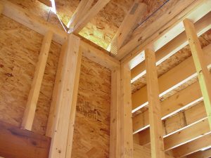
Framing members to which gypsum panel products are to be attached should be installed so that they are straight and true. Bent, twisted, cut, split, or otherwise damaged framing members should be not be used. The attachment surface of any framing, furring member or fastening surface shall not vary more than 1/8 in. (3 mm) from the plane of the faces of adjacent fastening points.
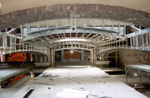
Cold-formed steel framing members with a base metal thickness from 0.0329 in. (0.836 mm) to 0.118 in. (2.84 mm) shall comply with AISI S240 – North American Standard for Cold-Formed Steel Structural Members or ASTM C955 Standard Specification for Load-Bearing (Transverse and Axial) Steel Studs, Runners (Tracks), and Bracing or Bridging for Screw Application of Gypsum Panel Products and Metal Plaster Bases.
Steel framing members should be straight, free of rust or other visible damage and should be installed based on the criteria of ASTM C754 for non-load bearing studs or ASTM C1007 for load-bearing studs.
Many installations incorporate the use of rigid furring channels or resilient furring channels. GA-216 should be consulted for specific criteria regarding the installation of rigid furring channels and resilient furring channels.
Panels should be applied first to ceilings and then to walls. This ensures that panel ends on ceilings will be properly supported by panels applied to walls.
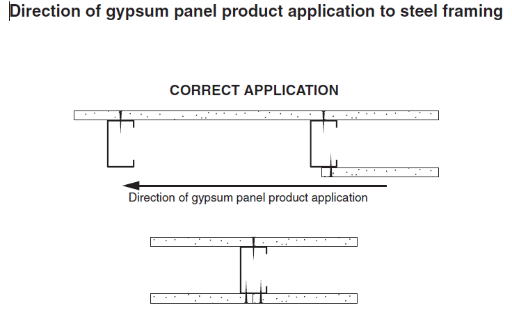
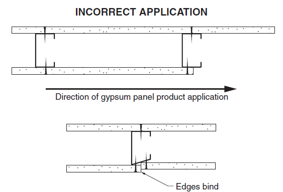
When installed to steel framing members, gypsum panels should be applied so the leading edge of each panel is attached to the open or unsupported edge of the steel stud flange.
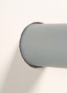
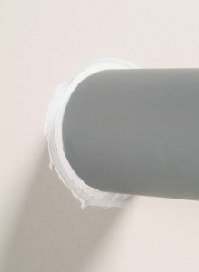
Holes, such as those for pipes, fixtures, or other penetrations, should be scored on both the face and back of the panel before removal of the cut-out with a saw. Holes may also be cut out with a router or other special tool designed for the purpose.
Holes should be neatly cut to the approximate size of the penetrating item. The annular space surrounding the penetrating item should be sealed as mandated by model code requirements.
Panels should be installed so that joints on the opposite sides of a partition do not occur on the same stud. Diagram A, below, illustrates the concept.
In single-layer gypsum panel product systems, end joints parallel to and on the same side of framing members shall be staggered from joints on the opposite side of the framing members.
In multi-layer gypsum panel product systems, end joints parallel to and on the same side of framing members shall be staggered between alternate layers of gypsum panel products.
In multi-layer panel systems, end joints parallel to and on the same side of framing members should be staggered between alternate courses of panels. Base layer end joints parallel to framing members should be staggered from end joints on the opposite side of the framing members. The diagram below depicts an elevation showing joint staggering between courses of panels on one side of a partition.
Additional requirements for base layer joints in wood-frame multi-layer systems are contained in Section 6 of GA-216. Note that the requirements for joint staggering may be superseded by a fire- or sound-test, or by specific structural requirements.

