An introduction to key terms, strategies and noise attenuation assemblies
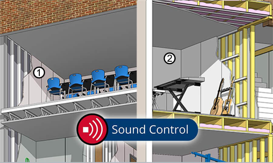
Sound Control is an important design consideration for both commercial and multi-family projects.
Just like many other characteristics of a structure that can be optimized for the benefit of its occupants, better sound performance may mean amplification in the case of a concert hall or attenuation in the case of a hotel room. No single sound-control strategy works for every structure. In fact, no one strategy will work in every space within the same structure. Appropriate sound solutions begin with a clear use objective for each space under design.For the purposes of this information, the focus is sound attenuation, recognizing that noise reduction between spaces in a structure is the primary objective of the wall and floor/ceiling assemblies proposed. In addition, the emphasis is on system solutions. That’s because no single material or structural component is capable of providing the entire solution on it’s own – realistically or cost efficiently.Finally, the information provided here just touches the surface. However, learning a few key terms and covering some common sound-control strategies demonstrates how gypsum panel products can be used as part of well-designed noise-control assemblies.
General Characteristics Of Sound
Sound or noise is the product of vibrations that radiate from a source such as a person speaking or a door closing. These vibrations or sound waves travel through the air and through surrounding materials to the ear where they cause the eardrum to start vibrating as well. The brain processes these vibrations as audible sounds.Two important sound characteristics are pitch and volume.Pitch – Pitch is often described as how high or deep a sound is and pitch varies based on the number or frequency of sound waves a noise source produces in one second. The higher the frequency, measured in hertz (Hz), the higher the sound pitch. The lower the frequency the deeper the pitch. Typically the human ear can detect sounds that range from 20 to 20,000 Hz with the highest note on a piano being about 4100 Hz, human speech ranging from about 150 to 3500 Hz, and the bass notes on a stereo from about 40 to 55 Hz.Volume – Volume is the loudness of sound and reflects the energy contained in a sound wave measured by the height or amplitude of the wave and stated in terms of decibels (dB). For example, a whisper is about 20 dB, normal conversation is 60 dB and jet engine noise is in the range of 120 dB. Reducing volume is one of the primary objectives of noise control and one of the main tasks in this process is to block or interfere with the effective transfer of sound energy from its source, through the air and the structure itself, to the occupants in the space.Sound Control Classification And Testing
The ability of a wall or floor/ceiling assembly to reduce the sound energy passing from one space through a partition and into an adjoining space is described in one of two ways:o For Wall Systems – The effectiveness of the assembly to inhibit “airborne” noise vibrations from passing through the wall is identified as its Sound Transmission Class (STC).
o Floor/Ceiling Systems – The ability of a floor/ceiling system to inhibit the sound of footsteps and other floor “impacts” from passing through the assembly into the space below is called its Impact Isolation Class (IIC).
In both cases, the higher the value the better the sound isolation performance.
Testing an assembly to determine its STC or IIC value can be done in the field, but laboratory tested assemblies predominate in building design and the following content includes only values based on laboratory testing.
o The Standard Test for Laboratory Measurement of Airborne Sound Transmission Loss of Building Partitions and Elements is specified by ASTM E90. This test produces a value measuring the assembly’s ability to reduce sound energy transmission from 100 Hz to 5000Hz for interior walls and 80 Hz to 5000Hz for facade/exterior assemblies.
o The Standard Test Method for Laboratory Measurement of Impact Sound Transmission Through Floor-Ceiling Assemblies is specified by ASTM E492. This test utilizes a mechanical device called a “tapping machine” to simulate floor impacts in a “source” room that are then measured for energy loss after passing through the floor/ceiling assembly into a “receiving” room immediately below.
STC and IIC values represent the optimal performance potential of a system measured in a controlled environment and may or may not represent actual performance in a real world application due to variations in materials and installation. These values do however provide a basis for assessing the comparative effectiveness of modifications to assembly components in an effort to increase a wall or floor/ceiling system’s sound attenuation properties.
Primary Sound Control Strategies
A number of different strategies may be employed to increase a wall or floor/ceiling assembly’s ability to minimize noise transfer. The best solution often involves a combination of tactics and techniques. Here are some key strategies to consider:
1. Plug The Gaps – Sound vibrations traveling through the air don’t just travel in a straight line. They bounce in every direction off the surfaces they encounter carrying noise down halls, over partitions and around corners through a phenomena called “flanking.” Because their energy is transferred from one air molecule to another, they can pass through any space air travels through such as the openings around electrical fixtures or pipes, small gaps at the top, bottom or sides of walls and under or around doors and windows. One of the easiest sound control strategies is to seal every gap, joint or penetration with an acoustic sealant or gasket material per ASTM C919 to prevent sound vibrations from flanking or transmitting indirectly through a wall or floor/ceiling assembly.
2. Increase Wall Mass – Sound waves lose energy or volume as they pass through the wall and floor/ceiling assemblies used to construct a building. Increasing the mass of walls and ceilings with additional layers of gypsum panels decreases sound energy because resistance to the transfer of those noise vibrations increases. This is another easy step to take because extra panels can be added to one or both sides of the wall without dramatic structural changes and still provide significant benefit.
3. Decouple Rigid Connections – Hard connections between the framing materials and the gypsum panels on either side of a wall create an easy and direct path for sound vibrations to travel. Modifying the wall, so that the gypsum wall panels on one side of the wall are attached to a different set of studs than the gypsum panels on the other side, provides greater sound attenuation. Either stagger the placement of the studs or use a double-stud arrangement to break this sound pathway. Another technique to break this direct structural coupling is to attach the gypsum panels on one or both sides of the wall to the studs using resilient channels, which also helps inhibit sound transmission through the header and base plates and adds flex to help absorb sound waves.
4. Add Air Space – To further decouple rigid connections between the gypsum panels that form the wall surface of one room from the gypsum panels that form the wall surface of an adjoining space, add more air space to the wall cavity to help reduce sound transmission.
5. Add Insulation – Adding insulation in the wall cavity has the effect of increasing the resistance to sound waves moving through the otherwise empty space from one room to the next, absorbing sound energy in the process. This strategy is most effective if the rigid connections from one side of the wall to the other have already been decoupled, otherwise the sound vibrations will flank the insulation by passing through the most direct route — the gypsum panels and framing.
6. Use Steel Studs – Steel studs are a standard building material for commercial construction and they are better than wood studs at reducing sound transmission because they are less rigid. For sound control purposes, a higher gauge (thinner) stud inhibits sound vibrations better than a lower gauge (thicker) stud.
Some strategies modify the quantity, dimensions, or characteristics of key materials. Other strategies make adjustments to the design, construction, or order of the components involved. Usually it’s the combination of several strategies that provide the most effective solution for your particular application. In critical or sensitive areas, such as concert halls, music studios, healthcare facilities, and schools consultation with an acoustician is recommended. Of course, before employing any strategies, make sure structural and other key performance attributes (such as fire resistance) will still be met.
Additional Considerations
While sound attenuation is an increasingly important design consideration, any changes to fire-rated assemblies must not affect the ability of a system to resist fire. Consult the General Explanatory Notes in GA-600, Fire Resistance and Sound Control Design Manual, to understand how to add insulation to a system without affecting fire performance. Also, the addition or deletion of insulation in a floor-ceiling or roof-ceiling system has the potential to reduce the fire-resistance rating. General Explanatory Notes 11, 12, 13 outline the requirements for insulation.
Some Practical Examples
To help make these ideas a little easier to understand, review these wall assemblies and see how applying some of the strategies above can make a significant difference. Keep in mind that for every increase of 10 points in the STC value, the volume of sound transferred through the wall assembly is reduced by 50%. Notice also the contribution made by adding layers of gypsum panels.
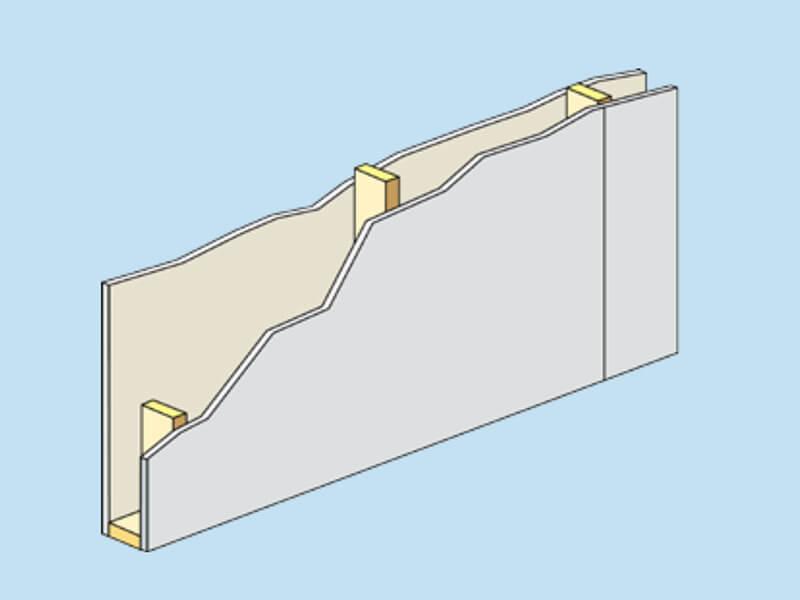
This system is the typical residential wall used in most new homes. A single layer of 1/2” regular gypsum board applied to both sides of a wall framed with 2” x 4” wood studs, 16” o.c. with 5d nails 8” o.c.
Test reference: NRC #66, CONC 1.2.1.1.4.1.
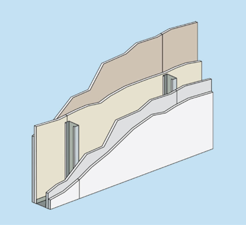
Base layer 1/2” Type X gypsum wallboard applied parallel to each side of 2-1/2”, 18 mil (25 ga.), steel studs 24” o.c. with 1” Type S drywall screws 12” o.c. at vertical joints and wall perimeter and 36” o.c. at intermediate studs.
Face layer 1/2” Type X gypsum wallboard applied parallel to each side with 4” wide strips of drywall laminating adhesive 2” from board edges and 4” off board centerline and 1-3/4” Type S drywall screws 12” o.c. at wall perimeter and 16” o.c. at intermediate studs. Joints staggered 24” each layer and side.
Test reference: RAL TL69-42
Base layer 1/4” gypsum wallboard applied parallel to each side of 2-1/2”, 18 mil (25 ga.), steel studs 24” o.c. with 1” Type S drywall screws 12” o.c.
Face layer 5/8” Type X gypsum wallboard applied parallel to each side with 1-5/16” Type S drywall screws 12” o.c.
Joints staggered 24” each layer and each side. Sound tested with 1-1/2” mineral fiber insulation, 3.0 pcf, friction fit in stud space.
Test reference: CK 684-14
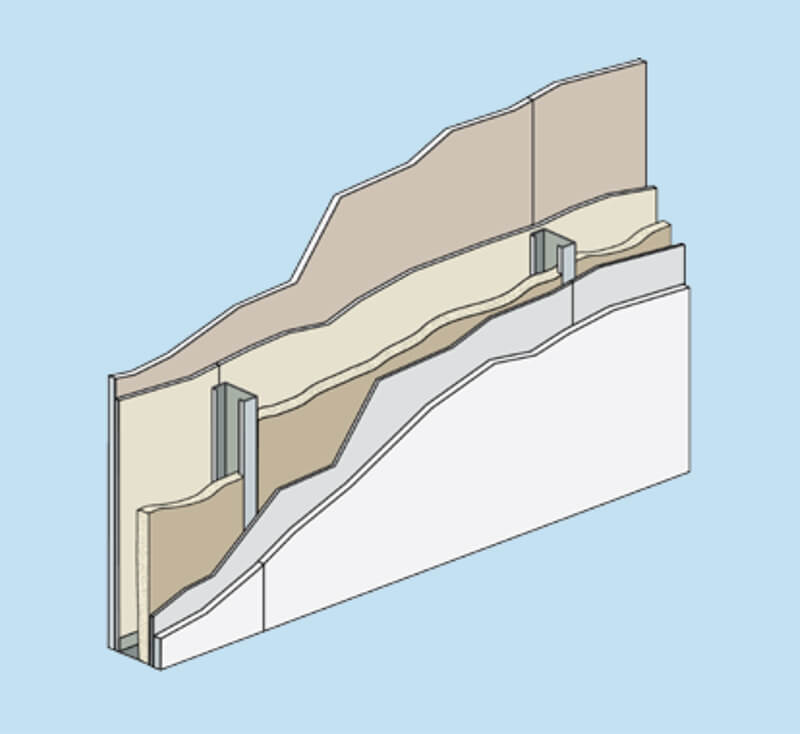
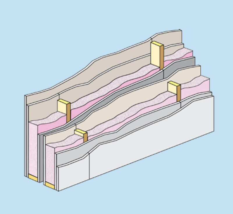
Base layer 1/2” Type X gypsum wallboard applied at right angles to 2” x 4” wood studs 24” o.c. with 6d coated nails, 1-7/8” long, 0.0915”shank, 1/4” heads, 16” o.c.
Inner layer 1/2” Type X gypsum wallboard applied parallel to studs with 6d coated nails, 1-7/8” long, 0.0915”shank, 1/4” heads, 8” o.c. Joints in inner layer need not be taped.
Second wall duplicate of first wall and separated by 1” space. Walls independently loaded.
STC 59 with 3-1/2” glass insulation friction fit in stud space both sides. STC 57 without glass fiber insulation.
Test reference: RAL TL73-215, RAL TL73-224
When optimizing the design of a wall or floor/ceiling for purpose of sound attenuation, there are a number of options and gypsum panel products can play a valuable role in achieving that objective. When considered along with their ability to contribute to improved fire safety, gypsum panel products are an effective and cost-efficient superstar in the sound control arsenal.
More Information
To find more information related to sound control and to review a large collection of wall, floor/ceiling, shaft wall and area separation wall assemblies that include gypsum panel products along with component descriptions and fire-, as well as, sound-test results, if available, refer to GA-600 Fire Resistance and Sound Control Design Manual or contact Gypsum Association member manufacturers. In addition, the National Research Council Canada has created soundPATHS – A web application that can be used to predict the sound transmission between rooms.
